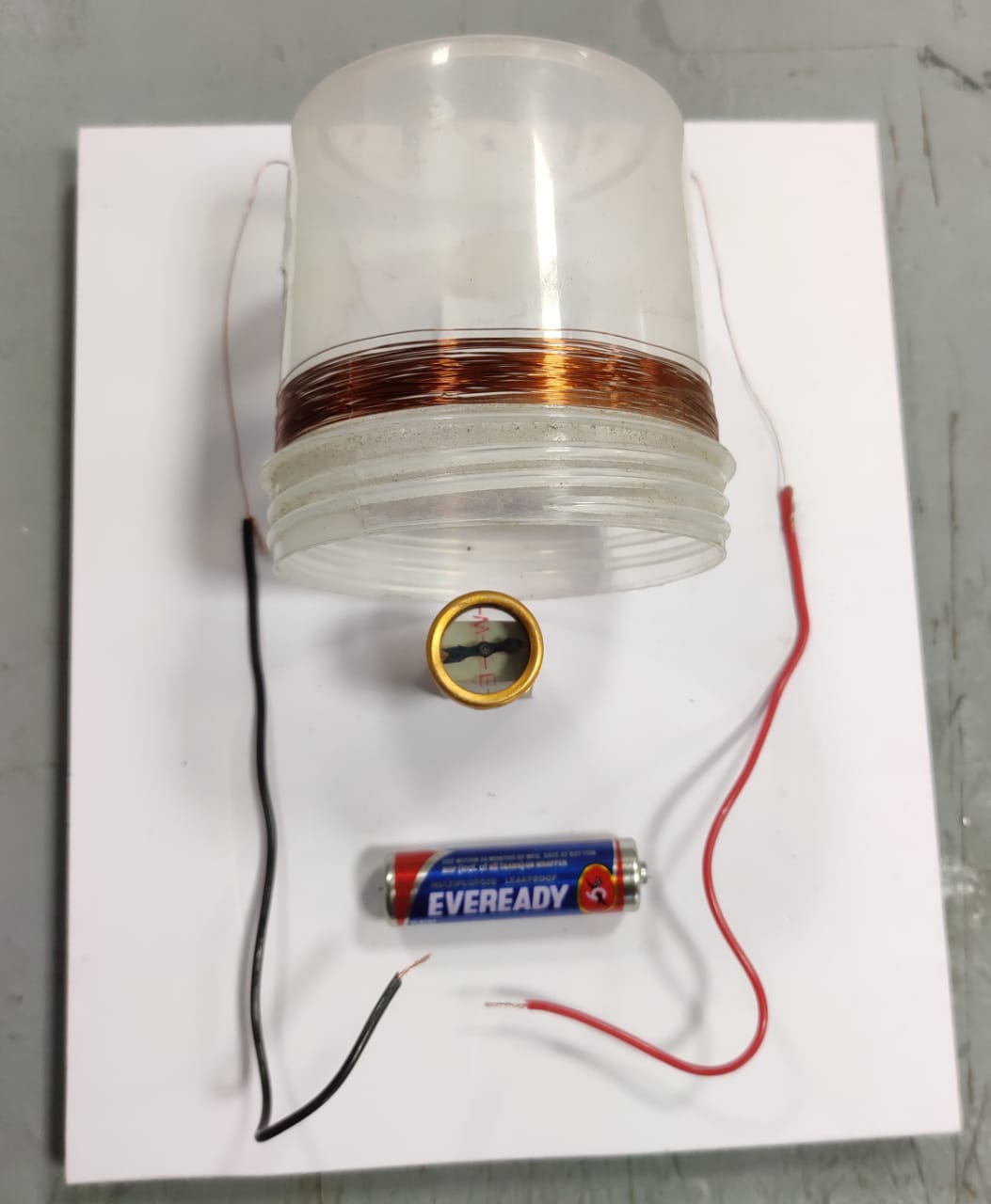
DO IT YOURSELF: MAGNETIC FIELD OF A CURRENT CARRYING SOLENOID KIT
Theory:
When an electric current is passed through a conducting wire, it produces a magnetic field around it. This was discovered by a Danish physicist named Hans Christian Oersted (14 August 1777 – 9 March 1851) in the year 1821. This was the first established convincing link between electricity and magnetism which were previously thought to be as seemingly two different subjects. When the wire is wound into several turns in the form of a Solenoid, the magnetic fields produced by the individual turns to get added up producing a high magnetic field. (A Solenoid is a long coil of wire wrapped in many turns and when a current is passed through it, it creates a nearly uniform magnetic field inside.) This is the basis of electromagnets which is now widely used in various electro-magnetic devices for many useful applications like motors and generators, transformers, relays, electric bells and buzzers, loudspeakers and headphones, magnetic recording and data storage equipment such as Tape Recorders, VCRs and Hard Disks. When the direction of the electric current in the circuit is changed, the direction of the magnetic field is also reversed.
Materials Required:
Toggle Switch- 1no
Magnetic Compass - 1 no
Enamel Coated Copper wire ( 34 swg)- 10 mtr
A cylindrical transparent plastic container to wind the Enamel Coated Copper Wire- 1no
Electric Cell (1.5 V) - 1 no
Feviquik Glue- 1 no
Cutting Knife- 1 no
Foam Sheet for preparing Base Board ( Size : 8" x4" x 5mm) - 1 no
Cello Tape- 1no
Flexible Copper Wire- 1 ft
Sand Paper- 1 piece
Eraser- 1 no
Construction
1. First, prepare the coil by winding the enamelled copper wire over the plastic container for nearly 30 turns. Care should be taken so that the wire is wound only in a single direction (clockwise or anti-clockwise) and the turns of the coil should not overlap with one another. Paste a layer of cello tape over the turns of the coil so that the turns do not get loose.
2. Mount the coil over the Foam Sheet baseboard with the help of feviquik glue.
3. Connect the two ends of the coil to the two flexible wires. For this, the enamel coating of the enamelled copper wire should be removed thoroughly by rubbing it several times with a sandpaper so that metallic copper will be exposed. It is important to understand that, unless the enamel coating is removed completely from the wire, no electrical contact made is possible.
4. Place the magnetic compass at one end of the coil with the help of feviquick glue. For getting better effect, the magnetic compass should be placed near the axis of the coil and, for achieving this; the compass should be placed at some height from the baseboard with the help of a supporting device like an eraser.
5. Mount the electric cell on the baseboard with the help of feviquik glue.
Now our kit is ready for experimentation.
Experiment:
1. Electric current is passed through the coil by temporarily connecting its two ends to the polarities of an electric cell (1.5 V). The needle of the magnetic compass will show a deflection on interacting with the magnetic field produced by the current flowing in the coil.
2. Now, reverse the direction of the current in the coil by changing the ends of the coil in the cell. You will observe that the deflection of the magnetic needle is also getting reversed.
Caution:
Don't pass current through the coil for too long a time. The electrical resistance of the coil being very small, this would lead to the flow of a large current in the coil resulting in short-circuit and overheating. Only touch and remove the two ends of the connecting wires of the coil to the cell and observe the deflection in the magnetic compass.
Inference:
A current-carrying conductor produces a magnetic field.
Nikunja Bihari Sahu
Education Officer
Regional Science Centre
Bhopal


Comments
Post a Comment